
Configure COM2 Port to RS485 Mode for Q30400X Series
This article covers full procedures to switch COM2 to RS485 mode for Q30400X series, including J1C2/J2C2 hardware jumper configuration, COM2 RS485 pin assignment, 120‑ohm termination resistor tips, and two troubleshooting solutions for serial‑port sequence disorder. Complete jumper and BIOS setup before RS485 testing.
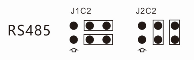
Switch COM2 between RS232 and RS485 via jumpers J1C2 and J2C2. Jumper locations: Item No.27 and No.28 as shown in the figure below.
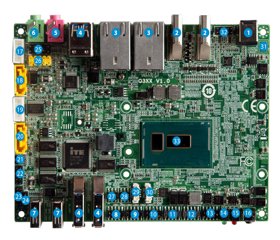
Item No. | Description | Jumper Label |
|---|---|---|
27 | RS232/RS485 Function switch jumper | J1C2 |
28 | RS232/RS485 Function switch jumper | J2C2 |
RS232/RS485 Function switch jumper (J1C2)
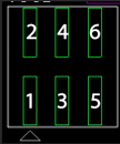
Function select | Connecting pins |
|---|---|
RS232 | 1‑3, 2‑4 |
RS485 | 3‑5, 4‑6 |
RS232/RS485 Function switch jumper (J2C2)
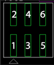
Function select | Connecting pins |
|---|---|
RS232 | 1‑2 |
RS485 | 3‑4, 5‑6 |
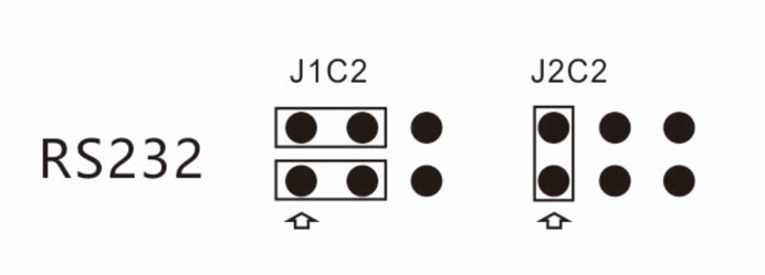
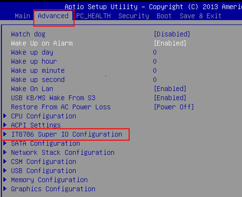
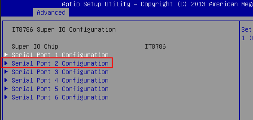
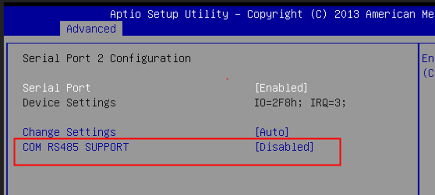
Software Configuration Press the DELETE key during power‑on to enter BIOS, then configure parameters as shown in the figure below.
When Item No.27 and No.28 are set to RS485 mode, the pin definition of COM2 is shown as below:
表格
Pin# | Signal |
|---|---|
1 | RS485‑ |
2 | RS485+ |
5 | GND |
Some RS485 devices require a 120‑ohm resistor connected in parallel between RS485+ and RS485‑ for proper operation. Depending on the connected device, it may be necessary to swap RS485+ and RS485‑.
Solution 1 for serial port sequence disorder issue: A. Deploy a freshly installed operating system. GHOST‑based system images are not supported.
Solution 2 for serial port sequence disorder issue: A. Manually assign COM port numbers from COM1 to COM‑6 sequentially in Windows Device Manager. B. Switch both the hardware jumpers and BIOS setting of COM2 to RS232 mode. C. Use a serial port test tool to map the logical COM number in OS to the physical COM port. D. After confirming the port mapping, re‑configure COM2 to RS485 mode for testing and normal use.